
As I mentioned earlier I designed some power amplifier for supporting my guitarist activity. What lead me to this hobby originated in the eighties. I was teenager then and had no money so I started to built simple guitar effects. Later as my knowledge developed, I begun making my own design what usually sounded better than the factory made circuits. Soon my interest turned to power amplifiers. I used a very poor sounding Regent 50G what was available then for the little money I had. Furthermore my father asked me to repair an old radio what used germanium power transistors which died. So I had two goals.
1. building a better guitar amplifier
2. repairing my father's old radio.
First I tried traditional schematics what helped me in the case of the old radio but didn't improved my guitar sound. As I examined deeply the problem I found that the traditional designs almost always use the power transistors as emitter followers, see below.
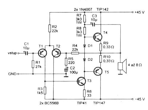
This is one of the most basic design of this area of electronics. In this configuration the power transistors amplify only current instead of voltage and current. Even it's true if complementer darlingtons are used instead of simple power transistors.This quite differs from the analogue case of tube amplifiers where the power tubes are allways used in grounded cathode configuration what results both voltage and current amplification.
Another problem with emitter follower configuration is that the power transistors need higher voltage drive than their emitters potential. It means that we cannot drive this kind of amplifiers's output to the whole range of power supply voltage without tricks. Necessarily its output must be less than supply voltage. If we applicate bootstrap then one power transistor's base ( T4) can be driven over the power supply voltage due to the fact that the bootstrap increase the driver voltage of this transistor over the positive supply voltage. But bootstrapping with capacitors results some problem about the phase transmission and I hear it as a strange squelch in the sound.
Nowadays everybody uses power mosfet transistors instead of bipolars. The widespread configuration of their using is quite similar to what we see above with some minor modification. They are more reliable than bipolar power transistors and sound better. In the other hand power mosfets need way higher drive voltage between their source and gate pole than bipolar transistors between their emitter and base. So the headrom is less if we use them in the traditional configuration.
In my case I wanted to upgrade an old, transistor powered Marshall amplifier. It had symmetrical power supply voltage +20V and -20V. Well it is quite low so I need all volts for my poweramp's output to produce as much power as it can be possible. I decided to use power mosfet transistors instead of bipolars due to their characteristic is similar to vacuum tubes. So I had to find a special configuration where I can drive my amp's output from negative supply voltage to positive supply voltage, so in the whole range.
It was obvious for me from the beginning that the traditional configuration did not provide this. After analyzing the circuit I realized that the way of using the power transistors must be changed. I need configure them in grounded source mode instead of source follower. In this case these transistors would amplify voltage too and so they need way less drive voltage for getting the headroom reaches the whole range between negative and positive supply voltage. This drive voltage can be provided easily. Another point that they must be stabilized thermally. The typical IRF type power mosfet's drain current is increasing by the temperature if the gate voltage remains the same. Studying the graphs I found that I must decrease the gate voltage by 5,5 mV per Celsius if I want the drain current being the same. Silicone transistors base-emitter opening voltage changes by -2mV so I have two ways. I can use three of them before every power mosfet or I can use one for only the one of the mosfets and I set the DC voltage circuit gain to six times. The negative feedback then arranges to share this compensation between the two mosfets so at the end we get -6mV/Celsius on every mosfet. Of course I need more AC gain in the circuit but it can be arranged easily by capacitors in a proper positions.
Another point was that I needed the default output level to 0V what is exactly the center between the positive and negative supply voltage. For this the most reliable solution is a differential amplifier (actually a long-tailed pair) at the front of the circuit. There are another options but none of them is stable enough. There is a debate about using long-tailed pairs in poweramps as it can be the source of annoying transient intermodulation distortion called TIM. In the other hand in the case of guitar amplifier which has a way narrower frequency range than a HiFi circuit this point is not so relevant, and as I keep the open loop AC gain also low, it seems this problem is fixed.
Though my design starts with long-tailed pair just like the traditional one the similarity ends right here. I use totally different thermal stabilization and bias than the classical. Also I drive the mosfets different way which are in grounded source configuration contrary to the classical solution. This arrangement provides full power headroom, high thermal stability with simple construction.
Let's see the schematic then.
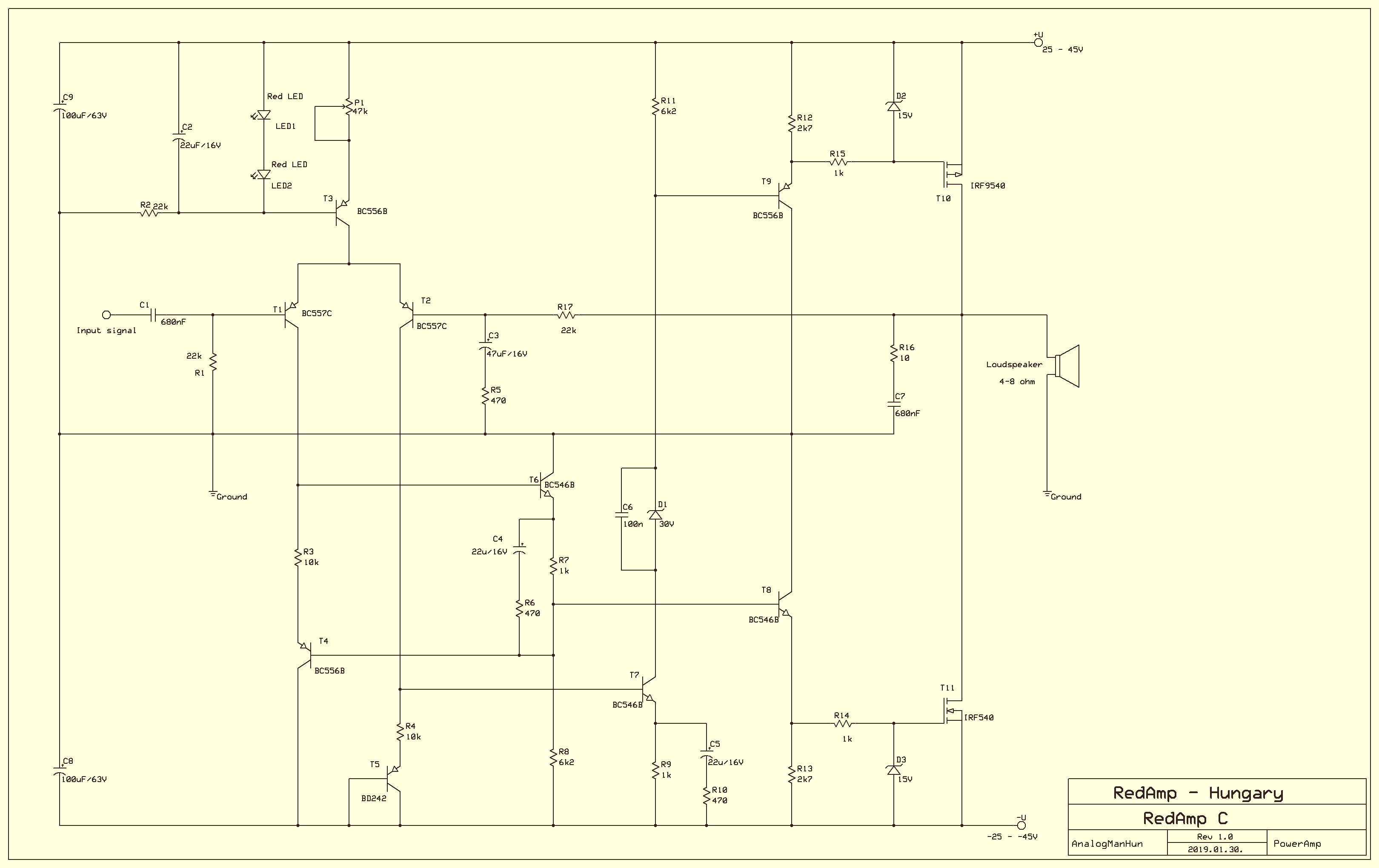
As the Figure 1 can be seen as the basic schematic of bipolar amps I think this Figure 2 has the right to be the basic schematic of mosfet poweramp technology due to its simplicity and because it uses all of the advantages of mosfet power transistors.
Let's see how it works. Practiced eye instantly recognises the usual long tailed couple (T1-T2) at the front of the schematic which works here as phase splitter. We use a current generator (T3) as emitter feeder for two goals. One point is it increases the amplifier's stability and symmetrical working. Second point that - instead of the practice of common bipolar amp circuits - we use it for biasing the output stage. My theory is that poweramp's DC gain shouldn't be enormous because we don't use it for amplifying DC but AC. Even more important principle that the power mosfets must be those parts where the biggest voltage (and current) amplifying should happen. For this goal I kept the DC gain of earlier stages as low as about 14 times. The long tailed pair amplifies only twofold and the second stage (T6,T7) does only less than sevenfold. Actually this is very good for thermal compensation. T5 is a transistor what must be applicated onto the heatsink the power mosfets are bolt on. So it is connected to them thermally. Every celsius grade increasing decreases the voltage on this part by 2 milliVolt. To stabilize a power mosfet thermally it needs 6 millivolt decrease on its gate by every celsius grade what means we have to amplify the decreasing on T5 voltage threefold. In the other hand it is enough only for the one of the two power mosfets (T10, T11) so actually we need sixfold DC amplifying after T5 then the negative feedback from the output takes care to share this compensation between the two.
As we see we drive the power mosfets by emitter followers (T8,T9). These provide low impedance which is good for fast charging and decharging the input capacitance of power mosfets (about 1-5 nF). In the other hand we use these capacitances to set the upper limit of frequency range this amplifier is working with. The human ear does not hear frequencies higher than 20kHz. It does not make sense to let this amplifier work with frequencies we even don't hear. Furthemore poweramps tend to produce unwanted feedback on higher frequencies what cases bad and unpredictable behaving of the circuit. So it is strongly suggested to limit the circuit to work only with that frequency range we hear. Or at least not so much wider range... That is why we drive the mosfets through R9 and R6 which consist low pass filters with the parasite gate capacitors of the mosfets.
We have not discussed only one interesting part of this circuit yet. This is a special arrangement of T4 and T6 transistors. It is quite rare to find this in circuits though it is not particularly complicated.
T6 seems to work in emitter follower mode. Actually it is wrong. It works in a grounded emitter mode but in this special case the ground is a floating one. The matter is that T1's collector sees T4's emitter as ground and the voltage what is a result of T1's current flows through R3 is relative to T4's emitter what is driven by that voltage what T6's current makes on R7 what depends on how much voltage of R3 drives T6 relatively to the voltage of R7.
Actually it is a kind of bootstrap but it uses transistor (T4) instead of capacitor. It results that T6 amplifies the voltage of R3 on R8 but contrary to the classical grounded emitter configuration it does it in same phase. The DC gain is the ratio of R8 and R7, the AC gain due to C3 capacitor and R6 is about 20. My theory is that the open loop gain of a poweramp - contrary to general beliefs - must be kept low because it prevents unwanted feedbacks and lets the mosfets express their good sound amplifying characteristics. It is also an effective method to avoid transient intermodulation (TIM).
We use this solution because we wanted symmetry between the two driver branch what lead to the two power mosfets. T7's role is unavoidable in this construction so I had to find a similar construction but with same phase amplifying in the other branch. That is why I used this special bootsrap solution.
So about the role of the zener diodes... This amplifier works with power supply +-25V to +-50V. There is only one transistor what is critical from this point of view. T7 works under almost the full voltage range from -U to +U. It means that the UCEOMAX of this transistor should be higher than this power range. In the other hand, BC546B's UCEOMAX is only 65V so we have to defend it from too much voltage. Actually it's collector voltage is not necessary be so high. What we need is its current what results voltage on R11. So we can separate the collector from this resistor by a zener diode what effectively decreases the voltage level at T7's collector. C6 shunts this zener's noise. Selecting the voltage of this zener diode there is one thumb of rule. The difference of the doubled supply voltage and the zener's voltage must be not higher than 60. For example if we use +-40 power voltage, the zener's voltage must be at least 20 Volt. If the power voltage is less than +-32V then rather leave out this diode and C6 capacitor by wiring T7's collector directly to R11.
D2 and D3 defend the gates of the power mosfets from too high drive voltage.
Of course the mosfets must be bolt on heatsink. The size of the heatsink depends on the power we want to get out of the amplifier. For 100 Watt you have to use +-40V power supply voltage. For 50 Watt the needed supply voltage is +-29V. If you want to use supply voltage higher than +-40 Volts I strongly suggest these:
1. use IRF640 and IRF9640.
2. double the mosfets. Use two IRF640 and IRF9640 instead of one. Use them in paralel position.
3. change the D1 zener to 50V zener.
Be sure that there is no short circuit between the mosfets and the heatsink. Use proper isolation parts.
P1 is responsible for setting the bias of the power mosfets. At the first run the variable pole must be set to the lower position what results that the trimmer's overall resistance is 47kiloohm. No we can roll carefully the pole slowly toward the upper position with very small steps. Meanwhile check the voltage between the source and the gate of T10. Around 3.3 Volt the mosfets start to warm up. Set a very little back the pole. Now we are at the safe bias level zone. Now we can attach the loudspeaker and give a signal to the input of the amplifier. If we still hear some harsh distortion then level up the bias a little bit. Though the amplifier is thermally compensated, it is not a magic tool. If we set the bias too high, the heat can kill the mosfets pretty soon so be careful.
The circuit is stable and relatively simple. It sounds differently to usual mosfet and bipolar poweramps, somehow more airy, but resembles to the famous VF2 circuit though more detailed and has better headroom.
Amplifier data:
Input resistance: 22 Kohm
Gain: 47
Open loop gain (without feedback): about 400. Depends on speaker's resistance.
Frequency range: 20Hz-30KHz
Output power: Depends on supply voltage. For 100W/8ohm, use +-40V. For 50W/8ohm use +-29V and leave out D1,C6, use simple wire instead of them. Do not use 4 ohm speaker if your power voltage is higher than +-33V.
This amplifier connects directly to the speaker so it is highly advised to use speaker defender circuit.
So download and print it. I use laser printer paper transfer method so if you use another method and have to mirror the pcb, do it yourself.
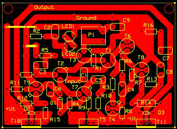
This is the component layout (the little pin on the transistor signs the emitter in this case):
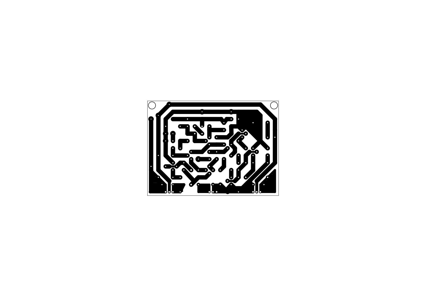
And this is the pcb layout for printer transfer method (I hope it keeps its size. unfortunately this site doesn't let me upload pdf so I choosed jpg format. Download it then print. This should be one A4 page size in your printer):
One note to the PCB. I did not wired R5 directly to the ground, because I wanted to let the possibility of current feedback stay opened. So if you used this pcb plan just simply connect the small pane at R5 left side to the ground pane as I signed with a short yellow wire.
Let me know if anybody has questions. And sorry about my bad english.
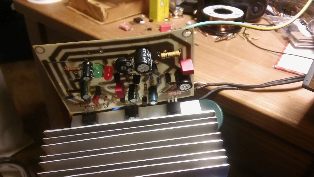
Testing...
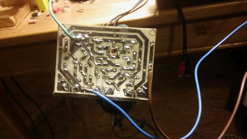
Backside...


A bejegyzés trackback címe:
Kommentek:
A hozzászólások a vonatkozó jogszabályok értelmében felhasználói tartalomnak minősülnek, értük a szolgáltatás technikai üzemeltetője semmilyen felelősséget nem vállal, azokat nem ellenőrzi. Kifogás esetén forduljon a blog szerkesztőjéhez. Részletek a Felhasználási feltételekben és az adatvédelmi tájékoztatóban.